Granular Media Filters
Granular media filtration is generally used after gravity separation. It removes additional suspended solids and oils before other treatment processes. It is also a polishing step that lowers the levels of suspended solids and associated contaminants in treated wastes. Particle removal takes place either on the surface of the media (cake filtration) or throughout the depth of the media (depth filtration).
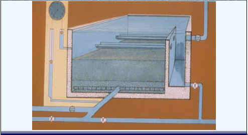
In the granular media filtration process, particles typically adsorb or attach to the grains of sand or anthracite in the filter. Below is a cross sectional drawing of a granular media filter. Solids removed from the water first accumulate at the surface and then penetrate into the filter bed. Water enters through the top, travels though the media, is collected in underdrain piping systems below, and eventually exits the filter and passes on to the clearwell or distribution system. As particles are removed in the media, loss of head occurs in the filter. Headloss increases due to accumulation of solids in the interstitial spaces and the corresponding increase in fluid velocity. Excessive headloss can lower the pressure within the bed allowing the release of gases from the water, `air binding'.
Cross Sectional Drawing of Granular Media Filter
The fundamental system that removes particulate matter is filtration, the most common filters are composed of granular media of certain sizes and depths. The forces that typically remove particles in granular media filters include:
Transport Mechanisms: Sedimentation--Density of particle is significantly greater than water and deviates particulate path from the water streamlines. Impaction--Inertia of particle is greater than hydrodynamic force. Interception--Particle remains in the fluid streamlines, but passes within a distance of half the particles diameter. Diffusion--Affects only colloidal particles (<1-micron) Dependent upon density, particle size, and flow velocity. Hydrodynamic--Not an important force with laminar (non-turbulent) flow, but basically particles are transported out the fluid streamlines to the surface of the media.
Adsorption--collection of particulate matter on the surface or interface zone of media. Short range surface forces. Can only be realized if adequate destabilization has been accomplished (functions similar to coagulation).
Absorption--taking in or absorbing contaminants. This mechanism is of little importance after the initial wetting.
Straining--Removal of particulate by passing liquid through a media with smaller pore sizes than the particles. Relatively unimportant because most of the particles are too small to be effectively strained.
There are several types of granular media filters:
Slow sand filters: These were the first filters used for treatment of public water supplies. They have a low loading rate (2 to 5 L/min /m2). Most of the solids are removed by straining at the media surface and in clogged interstitial spaces in the upper layers of the sand bed (termed the Schmutzdecke by German investigators). Filter capacity is restored by removing media and replacing it.
Rapid Sand Filters: These have a much higher loading rate of about 100 L/min /m2. Two criteria for termination of a filter run are excessive headloss and solids penetration through the filter. At the end of the filter run the filter is taken off-line and the bed material is backwashed. The clean water is pumped back through the bed to dislodge trapped solids. There is additional cleansing of the filter media by abrasion of particles on each other. The wash water is collected in troughs for removal and treatment or for removal and disposal.
Other filter types include: deep bed, upflow, pulsed bed dual and multimedia.
A slow sand filter consists of two or more filter beds containing 3 to 4 feet of sand placed over a gravel-supported underdrain. Most (if not all) of the materials of construction are often available locally, even in developing countries. As its name implies, a slow sand filter cannot filter a large flow of water in a small, contained filter assembly. Instead, it relies on a large surface area to filter a relatively slow flow of water (per square foot of filter area). Filtration rates of approximately 0.04 to 0.16 gallons per minute per square foot of filter surface area are typical. Therefore, a relatively large surface area is necessary to accommodate a realistic flowrate (for example, a 10-gpm flowrate requires between 60 and 250 square feet of filter surface area).
Slow sand filters can provide removal of suspended solids, turbidity, as well as microorganisms without the need for chemical addition or the use of electrical power. It will not remove all microorganisms, but removes a significant amount due to the formation of a rich biological matrix called a "Schmutzedecke." This layer consists of a wide assortment of life forms including algae, rotifers, and many other organisms. These organisms assimilate microorganisms (protozoans, bacteria and virus) thus reducing their numbers as water passes through the biologically active matrix. Slow sand filters are cleaned by draining the filter and scraping the top inch of sand (which includes the "Schmutzedecke"). However, this destroys the "Schmutzedecke" and requires a re-ripening period that can take weeks. While one filter is being cleaned, the other is on-line to continue the filtration process. In recent years, a new method of cleaning slow sand filters called "wet harrowing" has been developed that simplifies the cleaning process. Also, the creation and use of polyethylene filter vessel structures have made the task of building slow sand filters much easier.
It must be recognized that slow sand filters have their limitations in that they cannot remove high turbidity, high levels of microorganisms, nor chemical contamination from water.
There is a trend in Germany toward continuous sand filters. Stringent legal requirements on the level of suspended solids, phosphorous and nitrogen in discharged water have led German treatment plants to equip themselves with tertiary phases, consisting mainly of sand filters. The issue here has been which type of filter — the conventional, static, backwash or the newer, continuous operation sand filters.
Sand filters are used, first, for reducing the suspended solid content of the water before discharge. Secondly, they can also be used for bacterial and/or chemical removal of phosphorous and nitrogen. Carrying out these processes within the sand filter itself can do this or, if the processes are carried out earlier in the plant's process flow, the sand filter can be used to remove the flocs that they produce.
Advantages of continuous filters are: first, with the continuous filter you don't have the downtime required by backwashing. Secondly, the purchase prices of continuous filters are now competitive and, thirdly, the operating costs can actually be lower.
The filter produced by Kobe Steel is an example of a continuous upflow sand filter (see schematic below).
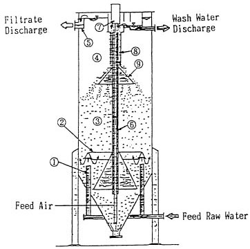
The filtration process begins as raw water ascends the filtration bed (3) via the raw water influent pipe (1) and raw water distributor (2). During this process, suspended solids are removed and the filtered water (4) collects at the filtrate through (5) and flows out as treated effluent.
The cleaning process is when the filter media which have caught suspended solids are sucked from the bottom of the air lift pipe (6) and cleaned while ascending together with air and water. The filter media is separated from the cleaning wastewater at the separation section (7), then further cleaned with the filtered water flowing opposite while it falls down through the special cleaner (8), and is uniformly scattered on the surface of sand layer by the sand distributor (9).
Rapid sand filter design considerations include size and uniformity of filter media which is specified using soils terminology. The effective size is the seize size in mm that permits only 10% of the media by weight to pass. The rationale for sizing filter media is as follows:
Fine material - problems with loss during backwash - good solids removal, but excessive headloss
Coarse material requires excessive backwash velocity, but little loss of materials during backwash
Uniform materials deep penetration of the filter bed by solids, but a greater chance of solids break through
Taking into account these criteria, sizing is a balance of considerations. Typical granular media is sand. Other granular materials used are anthracite, crushed quartz and garnet. The chart below shows typical design data for granular media filters used for the treatment of water.
Water Quality - Tchobanoglous and Schroeder typical depths, loading rates, material sizes
Filters may be single, dual, or multi media:
Single - sand or anthracite
Dual - sand and anthracite
Multimedia - garnet, sand and anthracite
After backwashing a single media filter the granular media settles back into place with the coarse materials (largest diameter) on the bottom, fine materials (smallest diameter) on the surface. This natural distribution causes solids to rapidly accumulate at the surface causing increased headloss and short filter runs. It is preferable to have trapped material accumulate more evenly through the depth of the bed to allow longer filter runs.
Dual and multimedia filters alter the gradation of the granular materials by using media with different densities. therefore these filters can have coarse (large diameter) materials at the surface due to lower density, and finer materials of higher density deeper in the bed.
Some intermixing of media is due to non uniformity of particle sizes and shape. This results in a non-uniform gradation from largest at the surface to smallest at the bottom (i.e. not the ideal). Rather, two or three accumulation surfaces will occur within the filter. However, this still permits greater utilization of the depth of the filter bed and therefore less headloss and longer filter runs.
The effectiveness of the granular material as filter media is dependent on the size, uniformity, and composition of the grains. The size of the granular media correlates with the surface area available to support the microorganisms that treat the wastewater. This consequently affects the quality of the filtered effluent.
Following is a schematic of sand or anthracite grains within a granular filter bed. The pores within the media perform very much like small sedimentation basins and the mechanisms discussed above work to remove particles as they pass through.
As more and more floc particles are removed in the pores of the media, the pores become smaller and smaller. This creates headloss through the filter and causes the velocity of the water traveling through the media to increase (assuming the filtration rate remains constant). This increase in velocity will cause corresponding increased shear forces and will eventually lead to break through of turbidity.
The underdrain systems support the filter media bed, collects the filtered water, and distribute the backwash water uniformly.
There are a large variety of underdrain systems many of which are proprietary. Most underdrain systems are overlain by gravel grades in five or six layers:40 to 60 mm diameter as the bottom layer
2.5 to 5 mm diameter as the upper layer
layers 60 to 200 mm thick, to a total depth of 400 to 600 mm
Distributors with lateral pipes equipped with nozzles or orifices are the simplest systems. Whatever system is employed, the backwash water must be distributed as evenly as possible to prevent jetting and loss of filter material during backwashing. Generally, there is provision under the filters for storage of treated water called the `clear water reservoir', `clear well'.
Typical removal efficiencies using granular media filtration are as follows:
Coagulation/flocculation/settling followed by granular media filtration
84 to 96% removal of turbidity
97 to 99.95% removal of coliform bacteria
100 removal of Giardia cysts
Without coagulation/settling
35 to 57% removal of turbidity
60% removal of coliform bacteria
80 to 91% removal of Giardia cysts
Poor process control can allow solids break through and escape of Giardia cysts. Use on-line turbidity or particle counting apparatus for process control.